BIM & 3D Piping Design: What Mechanical Designers Really Need to Know

BIM & 3D Piping Design: What Mechanical Designers Really Need to Know
Date: 03rd October 2025
Most people think they know BIM.
But when you scratch beneath the surface, especially in mechanical and piping design, it seems like a lot of people are still using the word without actually understanding what it means.
So, let’s break down…
- What BIM really is (and isn’t)
- Why Revit doesn’t always do the job
- What software and standards actually work for piping design in real-world plant environments
A guideline, not a rulebook…
You’ve probably heard someone say, “We’re doing BIM.” More often than not though, what they really mean is, “We’re using Revit.”
BIM isn’t a piece of software. It’s a way of working. It’s a framework for how different disciplines work together, share information, and keep everything coordinated. It’s about building smarter, not harder. It’s focused on things like:
- Coordinated 3D models
- Consistent, structured data (like the metadata)
- Making sure different software and teams can talk to each other
- Thinking about the full lifecycle of a project, from design to maintenance
But BIM doesn’t tell you how to design your piping system, or which flange spec to pick. That’s still down to your own engineering expertise and whatever software suits the job.
In short? BIM sets the standard. You choose the tools.
Why Revit Struggles with Process Piping
Revit is a powerful BIM tool but it’s just one of many. It’s not the full story.
Revit works brilliantly when you're designing building systems like HVAC, plumbing, or electrical. It allows for intelligent, parametric modelling and makes it easy to generate coordinated drawings and schedules; all great stuff in a building-focused environment.
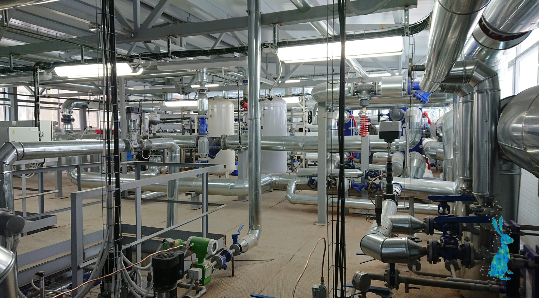
But when it comes to piping design for chemical or process plants, Revit often struggles. That’s because it was originally developed with buildings in mind, not the highly specific and technical requirements of industrial facilities. Process plants are a different beast entirely. They’re filled with skids, racks, pressure ratings, slope requirements, and strict, spec-driven design rules.
Revit’s architectural foundations don’t always align with that complexity. So while it can still play a role in your workflow, especially for coordination, it’s not always the right tool for the full job, particularly when the process side of the design takes centre stage.
The advantages of BIM
One of the biggest advantages of BIM is its clash detection capabilities, spotting conflicts between pipes, ducts, and structural elements before they turn into costly headaches on site.
But BIM goes far beyond just avoiding clashes. Every component in the model, whether it’s a pipe, valve, pump, or hanger, carries detailed information, or metadata, about its specifications. This means your digital model isn’t just a collection of shapes; it’s a database packed with useful data.
Even better, you can extract all this information into schedules or spreadsheets, eliminating tedious manual tracking of things like nozzle sizes or material specs.
In short, BIM models are much more than just “pretty pictures.” They’re intelligent, data-driven digital twins of your plant that can be queried, validated, and managed throughout the project lifecycle.
Picking the right tools
When it comes to tools, mechanical designers need to pick the right ones for the job. Revit works well for MEP coordination in building projects, especially when dealing with plant rooms in commercial or healthcare settings or when your models need to align closely with architectural layouts. Using Revit MEP alongside Fabrication Parts (which are lighter and smarter than traditional families) can improve control and performance, but beyond that, Revit starts to struggle.
Tools built for process plants
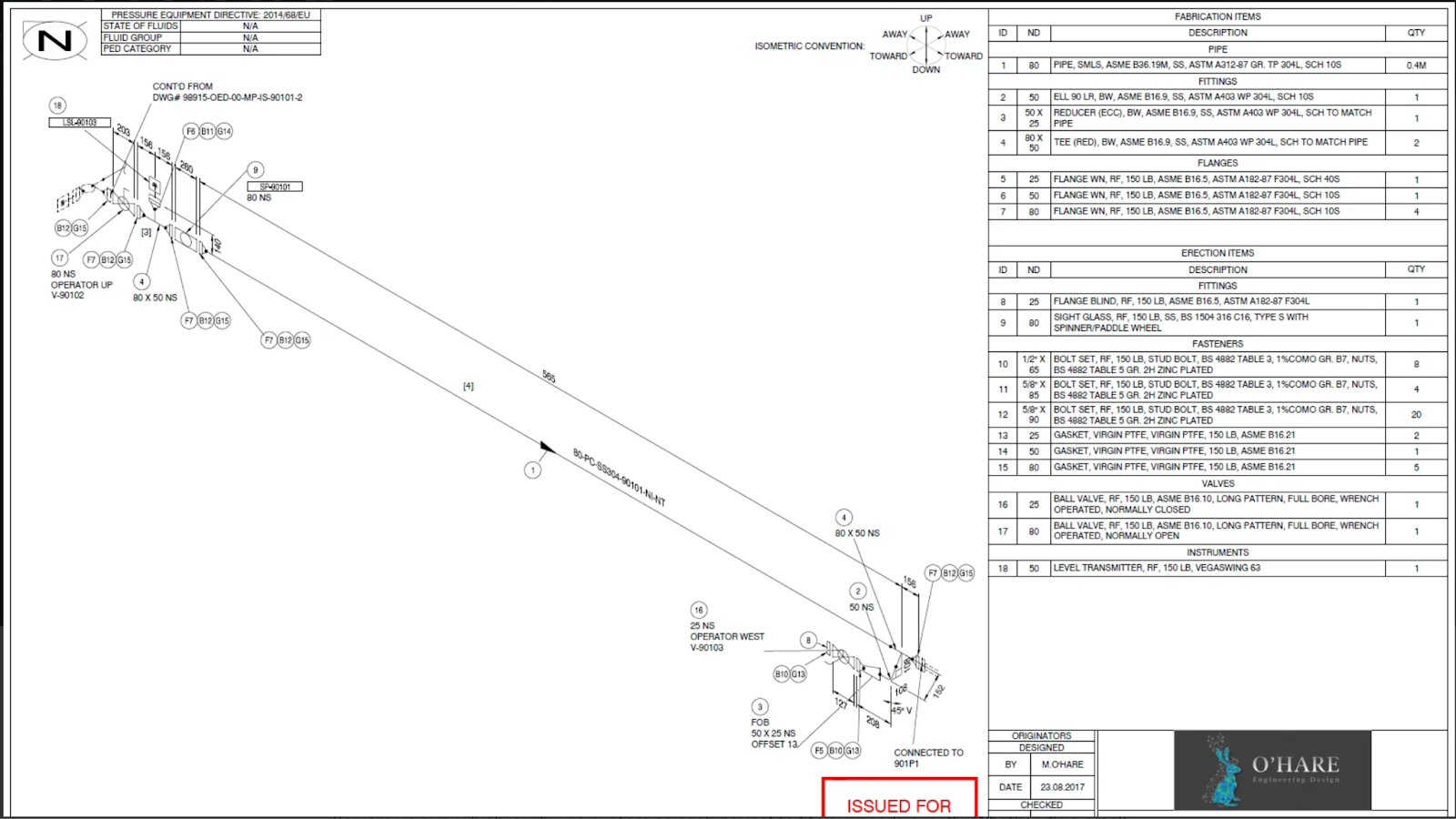
For plant designs like chemical plants, food, or pharmaceutical facilities, you’ll want dedicated tools built for the complexity of industrial piping. Platforms like Autodesk Plant 3D, AVEVA PDMS/E3D, MPDS⁴, CadWorx, and OptiPlant understand the intricacies of pipe specs, pressure classes, insulation, slopes, supports, and P&ID integration. These are designed to handle the technical demands that complex piping design demands.
The real power of BIM lies in its ability to integrate across disciplines allowing structural, mechanical, civil, and electrical teams to all work from one model to stay on the same page. Done well, this means fewer clashes onsite, smoother project handovers, and a digital twin that’s useful long after construction ends. But achieving this level of coordination takes the right software, communication, and effort.