How Accurate Is Accurate Enough With Laser Scanning Tolerances?

How Accurate Is Accurate Enough With Laser Scanning Tolerances?
Date: 01th December 2025
When you’re investing time and budget into a 3D laser scan or model of your complex chemical plant layout, it’s natural to ask the question: how accurate do we really need it to be? In practice, “perfect” accuracy is rarely achievable, and, just as importantly, it’s not always necessary. The key is to determine what level of accuracy is right for the job and finding the balance between cost, schedule and risk.
Why Accuracy Matters
It’s tempting to assume that more accuracy is always better. A higher accuracy point cloud or model gives you a closer representation of the real environment, which should, in theory, reduce rework and minimise surprises during design or installation. Yet every increase in accuracy comes at a price with longer scanning times, larger data sets, heavier processing, and more complex modelling. Beyond a certain point, the extra precision can add cost and time without offering any additional benefit.
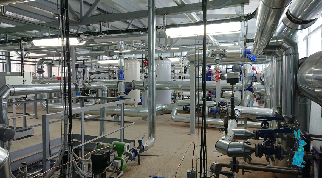
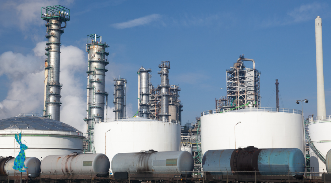
In a chemical plant, laser scanning may be used to capture pipe racks, vessels, platforms and supports to check what’s really there. The data might feed into new 3D models, help verify existing geometry before a modification, support prefab work, or simply guide future maintenance. But if the scan isn’t accurate enough, the new pipework might not fit amongst the existing infrastructure, clashes get missed, and you end up cutting and adjusting on site which is the last thing anyone wants. Go too far the other way, though, and you’ll burn time and budget processing data that’s far more detailed than the project actually needs. The aim is to always achieve a level of accuracy that’s genuinely fit for purpose.
Understanding Laser Scanning and Modelling Tolerances
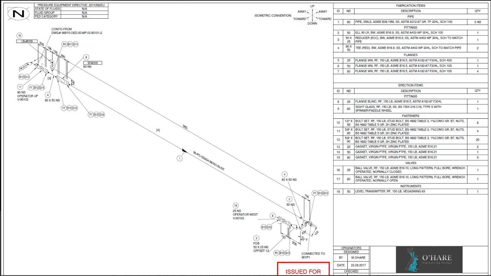
In laser scanning and modelling, tolerance defines the maximum allowable deviation between the captured or modelled data and the true geometry. Several things influence this including scan resolution (the spacing between points in the cloud), registration error (how accurately multiple scans are stitched together), modelling deviation (how closely the 3D model follows the point cloud) and environmental conditions such as vibration or temperature.
For example, if a scan has a tolerance of ±5 mm, that means the data is aligned to within five millimetres of the real position. When this data feeds into a model, that same degree of uncertainty flows downstream. Knowing these tolerances is helpful when deciding whether the data is suitable for detailed design, fabrication or construction.
Typical Accuracy Levels and Their Use
As a general guide, a tolerance of ±10–15 mm usually supports early-stage work such as feasibility studies or general layout modelling, where approximate measurements are sufficient to plan routes and clearances. A tighter tolerance of ±5 mm is often more appropriate for detailed design, clash detection and prefabrication of pipes where moderate precision is needed. For highly critical applications, such as retrofitting new equipment with minimal clearance, tolerances as tight as ±1–3 mm may be justified, though these are not always practical across an entire facility.
Importantly, the scan is only one part of a much longer chain. Downstream fabrication, welding, installation and even site conditions all introduce their own tolerances. There’s little sense in commissioning a ±1 mm scan if the installation tolerances on site are ten times larger. Matching the scan’s precision to the realities of the project avoids unnecessary cost and data complexity.
Deciding What’s “Good Enough”
The right level of accuracy depends entirely on how the data will be used. If you’re producing a conceptual study or checking general layout feasibility, a moderate tolerance may be all that’s required. For detailed design and prefabrication, the accuracy needs to tighten accordingly. Site conditions also matter: complex, congested areas with poor access may limit achievable tolerances, so realistic expectations should be set from the start.
The final step is quality assurance. Someone on your team or within the scanning provider’s team should confirm that the delivered data meets the defined “fit-for-purpose” criteria before it’s accepted.
Finding the Balance
In laser scanning and modelling, the question isn’t “what’s the highest accuracy we can achieve?” but “what level of accuracy do we need to make good decisions?”. By defining the use, understanding the working environment, aligning scan tolerance with fabrication and installation realities, and embedding QA processes early, you can ensure that your deliverables are both reliable and efficient.
At O’Hare Engineering Design Ltd, we work closely with engineers and project managers to define the right level of accuracy before scanning begins, ensuring that every dataset is genuinely fit for purpose. If you’d like to discuss how to set tolerances effectively for your next project, we’d be happy to help.