WHAT’S THE DIFFERENCE BETWEEN A P&ID AND PFD?

WHAT’S THE DIFFERENCE BETWEEN A P&ID AND PFD?
Date: 1st February 2023
Process Flow Diagrams (PFD’s) and Piping and Instrumentation Diagrams (P&ID’s) are both process engineering drawings used to explain process information at the design and manufacturing stage of any design project. At first glance, both contain relatively similar information.
So, why do you need both a PFD and a P&ID on a project? What are the differences? And when would you use each diagram within the engineering design process?
What is a Process Flow Diagram (PFD)?
A PFD is a document that is created at the start of the design process to show the equipment required, how everything in the system connects and most importantly indicate the direction of chemical flow. In a PFD, all of this information should be able to be read and understood at a glance.
What are the key components of a PFD?
Every PFD should contain the following information…
- Pipe lines which explain the mass, energy balance, flows, temperatures and composition of streams.
- Main Equipment
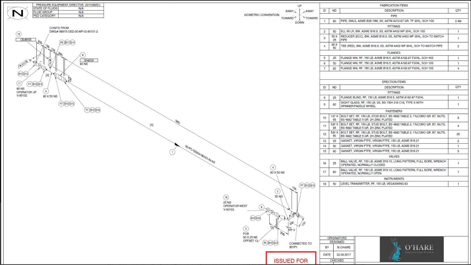
What is a Piping and Instrumentation Diagram (P&ID)?
Where a PFD provides a top level overview of your design, a P&ID will provide a much more detailed diagram of how your system will work and how it will work in relation to the rest of the plant. This is used by design engineers to source materials and map out the route for the proposed pipework to enable accurate and efficient manufacturing of the system.
What should be included in a P&ID?
As a P&ID is far more detailed than a PFD, there are many more components required within the documentation. This includes;
- Pipe size, line number, material, insulation
- Utility lines, drains and vents
- Isolation and shut off valves
- Instrumentation and its signalling
- Pipe lines which explain the mass, energy balance, flows, temperatures and composition of streams.
- Control loops
- Isolation and shut off valves
- A basic equipment list for the design, such as pumps and heat exchangers.
Why do you need both a PFD and a P&ID on the same project?
Although both of these process engineering design drawings are relatively similar, both are required on a job because they are both required by different people at different stages of the design and manufacturing process. A PFD for example shows how the system will function during operation so will usually be used during the design, proposal and ongoing maintenance phases of any project. A P&ID however shows how the equipment will function and connect within the site as a whole. This is required within the conceptualisation, procurement and manufacturing stages of a design project.
For more information about the process engineering drawing services we can offer, take a look at our mechanical design page or get in touch with us today.